I must apologise for not having written much lately. While I have been busy with other things, there has been progress on the model railway, but it has not been the sort of progress that would make an exciting piece of video! Having completed the platform canopy installation last month I have been doing thorough running tests and uncovering little snags, literally, here and there where the pantographs of some locomotives catch on the overhead installation or fitted snowploughs catch on trackwork, so I have been taking some time adjusting all these little things to ensure smooth running before I move on to the next major project.
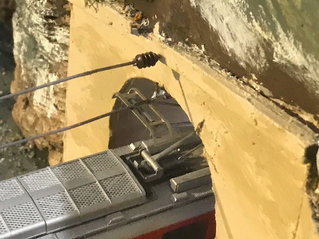
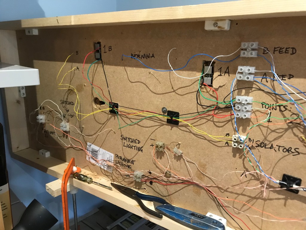
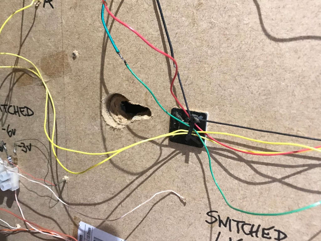
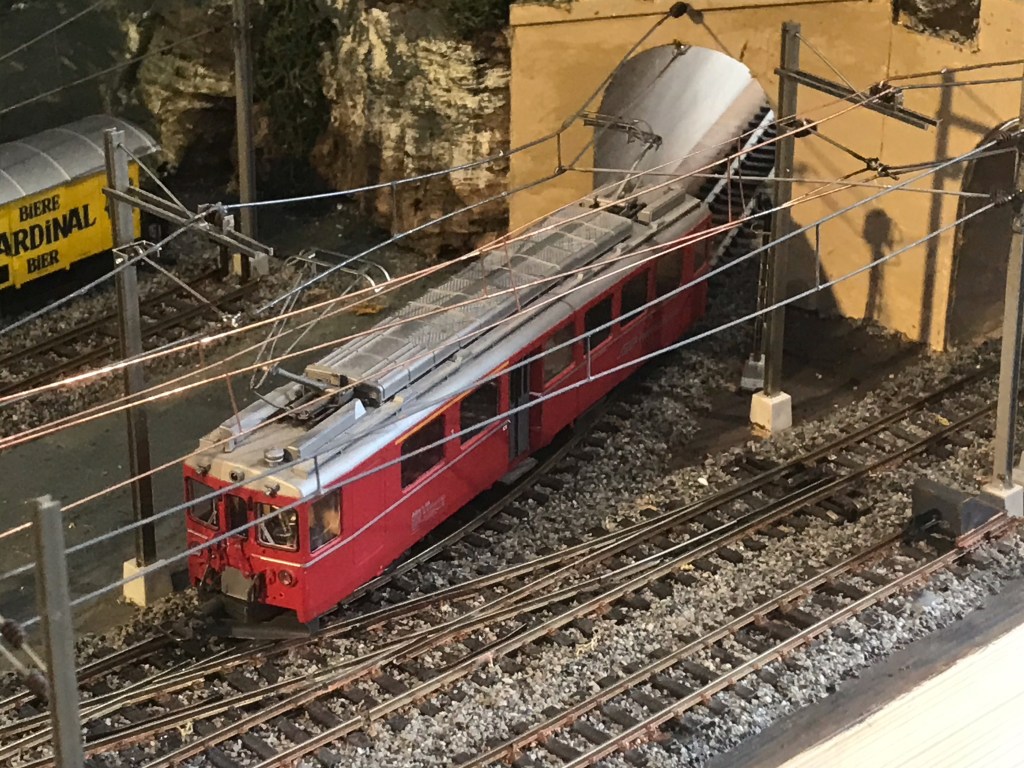
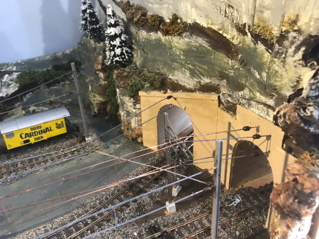
While I have been doing this, though, I have also installed the overhead through the second tunnel from Innsdorf station and including that in the snagging project, as well competing the cosmetic bits and pieces missing from the overhead where it meets the tunnel portals. Photographs of these jobs are included here for your interest.
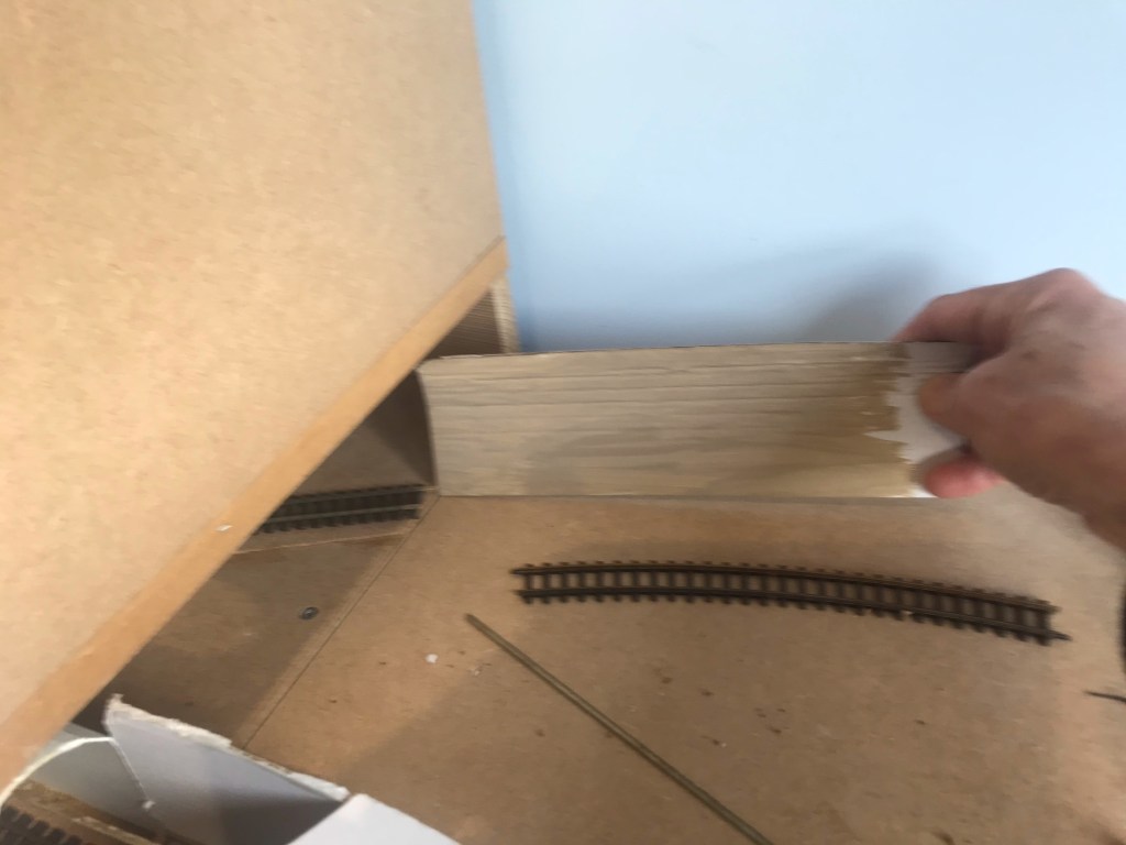
The next major project will be the construction of the first of the curving gradients up the mountain pass. I must lay the track for this before building any more mountain scenery, and I need to buy some suitable sheet material for the track base, perhaps plywood or thin MDF. I shall try to get this started in the next few days. The experience gained when building the branch line on my OO gauge Burghley Junction layout will be of great benefit in this project.
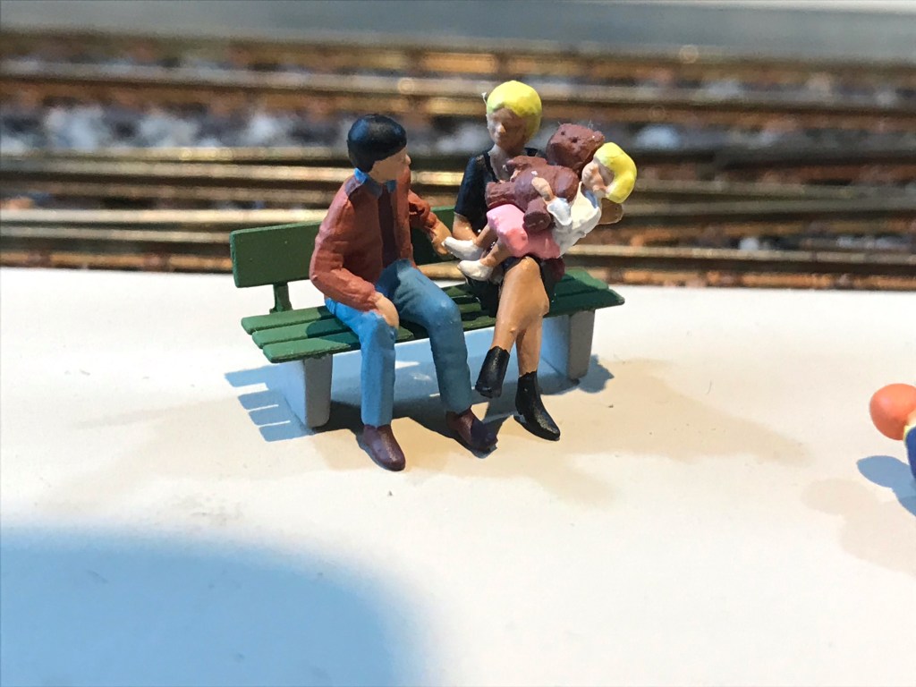
I still have jobs to do in and around Innsdorf station and the village so things are still moving on there as well – pictures and video to follow in due course.
Also, though, it will not be long now before real-life train travel will recommence and I shall be absent for a few days at a time, over on mwtrips.co.uk!